Optical Flowcells
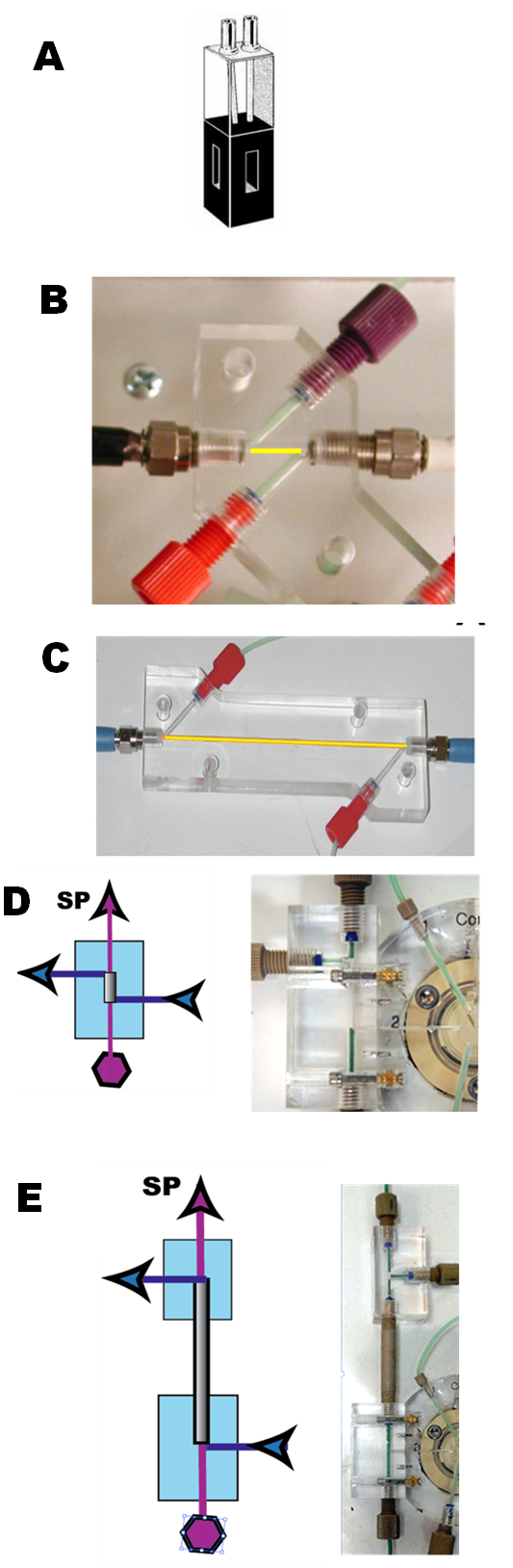
Fiber optics revolutionized design of Flow Injection instruments by facilitating the placement of a flow cell in the best position on a flow path. While in earlier generations of FI instruments the flow channel had to be long enough to reach inside into a bulky photometer, equipped with a flow through cuvette (A) the present designs use optic fibers to connect a flow cell situated on an optimized position on a flow path, with a light source and a spectrophotometer. This freedom of configuration also led to development of long optical path flow cells for UV-VIS spectrophotometry and chemiluminiscence.
The use of fiber optics also influenced flow cell design. Thus for UV-VIS spectrophotometry, while in the past the 1 cm long light path of an 80microL volume flow trough cuvette was the only choice, there are now low volume fiber optic flow cells available, offering a light path range between 0.01 cm and 25cm. Thus, by changing a flow cell, the response can be adjusted to the concentration of analyte within almost three order of magnitude.
As to construction, there are two types of flowcells:
- Free standing flowcells that can be used for any type of analyzer
- Flowcells integrated into lab-on-valve module.
Example of a free standing cell is the Z-cell shown here with 1cm (B) and 10cm (C) light path. These cells are connected to light source and spectrophotometer by quartz fiber optic cables (not shown) terminated by cell at fittings and equipped with a sapphire window. These flowcells can be disassembled for cleaning.
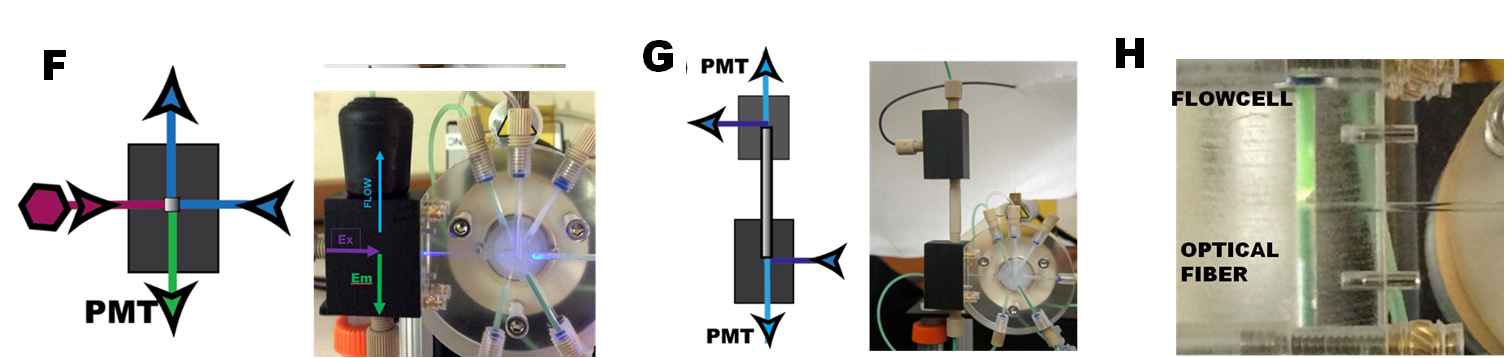
The advantage of integrating flowcell into lab-on-valve module is that the flow path of sample from injection point to detection is well defined, and its volume is minimized. The most recent construction allows the flow cell to be detached from LOV module, the feature which facilitates switching between flowcells of different functionality. This makes LOV module compatible with 15mm (D), 50mm, 100mm (E) and 200mm long light path cells as well as flow cell for fluorescence (F) and chemiluminiscence (G). The principal difference between these, so called Garth flowcells and the conventional design (B, C) is, that the polished end of quartz fiber optic cable is in direct contact with the fluid in the flowcells and for the long light path design is perfectly centered with a PEEK tubing that forms the flowcells light path (H). Further details on function and construction are in Sections 1.4.11., 1.4.14., 2.3.6., 2.3.9.A., 2.3.11. and 2.2.42.D.
1.4.10.